
Reinforced concrete inspection and corrosion protection
Half-cell surveys to ASTM C876, diagnosis of rebar corrosion, sacrificial anodes and cathodic protection, on tanks, rafts and marine structures.
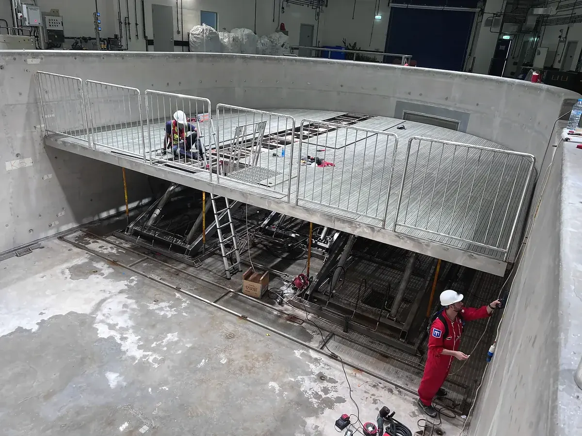
Corrosion starts long before the cover cracks
Chlorides and carbonation work in silence inside reinforced concrete. The first signs are measurable long before the cover cracks or a leak appears. MAREX inspects reinforced concrete in seawater and aquatic environments: tanks, basement rafts, marine and coastal structures, and the concrete that supports acrylic viewing panels.
We map corrosion activity, measure cover, carbonation and chlorides, take cores for the laboratory, and recommend protection. That protection may be sacrificial anodes or another form of cathodic protection, installed as a cure on a structure already in service, or designed in at construction with electrodes for later monitoring.
We act as an independent expert: we only carry out repairs with the agreement of all parties, with no conflict of interest.
How reinforcement corrodes in concrete
In sound concrete the pore solution is highly alkaline, with a pH of about 13. In that environment the steel is covered by a thin film of passive oxides. Two agents commonly destroy that film: carbon dioxide, which lowers the pH of the cover, and chloride ions from seawater or de-icing salts, which break the film down directly.
Once the steel is depassivated, expansive corrosion products form. They crack and then spall the cover, which accelerates the process. In some cases, flowing water washes the oxides away and no swelling is seen, even though section is being lost. That is why seepage water itself is worth analysing: dissolved iron is a sign that the reinforcement is already corroding.
What a MAREX corrosion survey includes
Field measurements and laboratory tests are combined. No single reading is treated as a diagnosis on its own.
Half-cell potential, ASTM C876
Potential difference between the reinforcement and a Cu/CuSO4 reference electrode on the wetted surface, plotted as an isopotential map.
Cover depth and bar location
Electromagnetic covermeter or scanner to locate bars and measure cover (B2-1, E2-1).
Carbonation and chlorides
Carbonation depth on split cores with a pH indicator (B2-2). Chloride profiles from powder samples or colorimetry on cores (B2-3, B2-8).
Resistivity, corrosion rate, cores
Surface resistivity (B2-6), polarisation resistance for corrosion rate (B2-5), and cores for laboratory analysis (A1-1).
Half-cell potential mapping
A high-impedance voltmeter (10 MΩ minimum) measures the potential between a connection to the reinforcement and a saturated copper/copper-sulphate electrode placed on the wetted concrete. The surface must be electrically continuous; a coating that insulates, or concrete that is too dry, makes the method unusable.
Older readings were often compared with the threshold values in ASTM C876-91: above −200 mV, a low probability of corrosion; below −350 mV, a high probability (Cu/CuSO4 scale). Experience has shown that those single thresholds are not reliable on their own. RILEM TC 154 advises interpreting potential gradients rather than absolute values. ASTM C876-09 is also based on isopotential maps, while still quoting the earlier thresholds.
MAREX therefore presents a map of potentials, checks electrical continuity, and confirms selected points by opening to the steel where it is justified. The survey is read together with cover, carbonation, chlorides, resistivity and, where useful, corrosion rate.
Sacrificial anodes and cathodic protection
Once the diagnosis is in place, protection can be specified. Cathodic protection, including sacrificial anodes, may be curative or planned from the design.
Curative, on an existing structure
Where corrosion is already active, sacrificial anodes can be added to protect the reinforcement that remains. The extent of the system follows the map of activity, the chloride profile and the condition of the cover. Sheet D1-1 places cathodic protection among the preventive or electrochemical treatments that may follow a corrosion diagnosis.
Designed in at construction
On new tanks, rafts and marine structures, anodes and reference electrodes can be provided in the pour. The electrodes support later half-cell surveys and long-term monitoring, without waiting for rust staining or leaks to appear. This is a design choice, not a repair.
What you receive
The deliverable is a signed inspection report, not a verbal summary.
- An isopotential map of half-cell potentials, read together with cover, carbonation and chlorides, and confirmed at selected points where opening to the steel is justified.
- Findings ranked by priority, with recommended actions and a recommended interval for the next inspection.
- Where protection is needed, a staged plan: further survey, re-sealing of active leaks where relevant, sacrificial anodes or another form of cathodic protection, and monitoring.
- Laboratory analyses of concrete and of water that has migrated through it, when they complete the field work.
- A response to every request for proposal within 24 hours, followed by a structured technical and commercial proposal.
What this changes for the operator
Activity mapped while the cover still looks sound
Chlorides and carbonation work in silence. The first signs are measurable long before the cover cracks or a leak appears.
No unnecessary shutdown
Surveys are planned with the owner or contractor, underwater or in the dry, without shutting the facility down when that is not required.
A signed, traceable report
Maps, photographs, laboratory results and ranked recommendations are recorded in a report that can be used by the owner, the contractor and the insurer.
A response within 24 hours
Every request for proposal receives a response within 24 hours, then a structured technical and commercial proposal.
Leaking basement raft, reclaimed land, Dubai
On a basement raft in a Dubai development on reclaimed land, seepage water contained about 6,000 mg/L chlorides, up to 1,730 mg/L sulphates, and dissolved iron, a sign of active rebar corrosion. Construction joints relied on injection hoses only, with no passive waterstops. Resin injection treated the leak, not the corrosion already under way behind it.
The staged plan recommended half-cell potential mapping to ASTM C876, cores for chloride profiles, re-sealing of active leaks with hydrophilic grout, cathodic protection of the reinforcement and permanent corrosion monitoring.
Context
Basement raft on reclaimed land in Dubai, in salt-laden groundwater.
Method
Review of the mix design, the waterproofing details and the contractor answers, and laboratory tests on the seepage water.
Finding
About 6,000 mg/L chlorides, up to 1,730 mg/L sulphates, and dissolved iron. Construction joints with injection hoses only, no passive waterstops.
Next step
A staged plan: ASTM C876 mapping, chloride profiles, re-sealing, cathodic protection and permanent monitoring.
Protocol sheets that inform this work
The sheets below are MAREX method sheets. They are listed as method references. They are not offered as a public download on this site at this stage.
- B2-4Half-cell potential measurement of reinforcementASTM C876, isopotential maps, Cu/CuSO4 electrode.
- B2-1Cover depth and reinforcing bar diameterLow-frequency electromagnetic covermeter survey.
- B2-2Carbonation depth of concretepH colour indicator on split cores.
- B2-3Powder sampling for aggressive agentsIncremental drilling for chloride and sulphate analysis.
- B2-8Chloride penetration by colorimetrySilver nitrate on split cores.
- B2-5Corrosion rate of steel in concretePolarisation resistance, instantaneous corrosion current density.
- B2-6Concrete resistivity and corrosion riskWenner surface resistivity and cover resistivity.
- B2-7Air permeability of surface concreteVacuum-cell measurement of the cover concrete.
- A1-1Concrete coringHardened samples for observation and laboratory tests.
- E2-1Locating reinforcementCovermeters and scanners compared.
- D1-1Diagnosis of corrosion in reinforced concreteMechanisms, modelling and the three-stage diagnosis.
Related reading and the next step
ASTM C876 for the operator
Why a half-cell survey is read as a map, not as a single threshold.
Read the note → SpecialityWaterproofing coatings inspection
Adhesion, continuity and singular points on the same tanks, rafts and pools.
View the service → Next stepRequest a proposal
Send the scope, drawings and timeline. We respond within 24 hours.
Request a proposal →Planning an inspection programme or a tender?
Send us your scope, drawings and timeline. We return a structured technical and commercial proposal.